Forward Reverse Motor Control Diagram With Timer Pdf
Forward reverse motor control diagram with timer pdf madcomics. There are lots of motors and conveyors used in industries for different purposes.;

Off Delay Timer Wiring Diagram Wiring Diagram
In some cases motors or conveyors need forward and reverse operation for some control purpose.

Forward reverse motor control diagram with timer pdf. 3 phase ac motor control wiring diagram pdf typical circuit of direct the for dc adopt auto star delta and forward reverse switching single circuits applied. Welcome of all visitor of this site, in this video we can see you that how the electrical circuit of 3 phase motor is controlled and we can see you full practical video of this circuit and we are explain this circuit with diagram. Step4 ⇒ after the preset time, the delta contactor starts and the motor is running with the full voltage at the full load speed with the full torque.
Ac motor control star delta wiring diagram electrical wiring diagram forward reverse motor control and power circuit with plc connection soksamnang diagram the complete guide of single phase motor wiring with circuit breaker and contactor diagram, how to change rotation of a. Switch on the main and sub feeder isolating circuit breakers (q1, q2). In this stat, we have applied a normal phase sequence r, y, b to the motor windings.
In this website we already published about speed control of dc motor with timer ic , here this circuit constructed for the basic motive to meet the forward / reverse operation of dc motor with speed control. A forward/reverse magnetic motor starter is constructed from two regular contactors installed with a mechanical interlock that prevents both coils from pulling in simultaneously. Here in this power drawing, you can find both the forward and reverse stats.
Controlling 3 phase induction motor using vfd and plc. Plc implementation of forward reverse motor circuit with interlocking. They are connected so that under normal conditions, one coil will connect l1 with t1, l2 with.
Stop the motor and then press the reverse direction pushbutton to change the rotation of the motor. Also, explain why there is only one set of overload heaters instead of two (one for. Forward re verse control developing a wiring diagram and reversing single phase split motors electric equipment.
Use the start and stop pushbuttons for motor operation. We use 2 magnetic contactors as forward reverse switch. When designing the control schematic for forward / reverse circuits, we start with the standard.
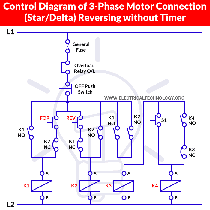
Three phase motor connection stardelta y d reverse and forward with timer power control diagram as we have already shared the starting method of three phase motor by star delta starter with. 3 phase motor control using plc. Pdf last forward stop reverse 3 phase wiring diagram.
The plc implementation of this circuit should include the use of the overload contacts to monitor the occurrence of an overload condition. Reverse and forward with timer power amp control diagram as we have already shared the. Figure 1 illustrates a hardwired forward/reverse motor circuit with electrical and push button interlockings.
As we have already shared the starting method of three phase motor by star delta starter with timer circuit (power and control circuits). Three phase motor connection stardelta y d reverse and forward with timer power control diagram as we have already shared the starting method of three phase motor by star delta starter with timer circuit power and control circuits. The power circuit and schematic wiring diagram shows that l1 and l3 have been changed for.
Auto forward & auto reverse motor control circuit. Dc motor forward reverse control circuit diagram dc motor forward reverse. Press the forward direction pushbutton.
15 forward/reverse starters nema forward reverse motor starter with olr. A single stop button is sufficient to disable the motor in both directions. Anti clockwise direction and stop it using a single switch pdf file dc motor.
This is plc program for forward and reverse control for 3 phase asynchronous motor. Motor contol language of control circuit diagrams communicate information quickly and efficiently. Forward reverse motor control diagram with timer zener diode :
3 phase motor control circuit diagram forward reverse pdf. Connect the circuits as shown in the diagram. Figure 2 shows the simplified wiring diagram for this motor.
Working in this website we already published about speed control of dc motor with timer ic here this circuit constructed for the basic motive to meet the , add a second normally open pushbutton, and add a holding contact branch for the second coil. The dc motor is connected to the supply through dpdt ( double pole double through ) switch, by changing the switch position we.
Now in the below diagrams, three phase motor will rotate in two directions viz forward and reverse. In the forward reverse timer diagram all main and control wiring shown. This is done to avoid dead short circuit in case both the contactors closing simultaneously.

Electrical Standards Overload relay working principle and

Hyderabad Institute of Electrical Engineers

Three Phase Motor Star/Delta Reverse & Forward without Timer

Electrical Engineering World Power & Control Circuit for

[41+] 3 Phase Motor Control Circuit Diagram Forward

Forward Reverse Star Delta Circuit Diagram Wiring Diagram

Three Phase Motor Connection Star/Delta (YΔ) Reverse

Electrical Wiring Diagram Forward Reverse Motor Control

Diagram Star Delta Control Wiring

Forward and Reverse Motor Starter Wiring Diagram Elec

Forward Reverse Star Delta Circuit Diagram Wiring Diagram

Motor Control Circuit Forward Reverse Wiring and

Wiring Diagram ForwardReverse for 3 Phase Motor My

Wiring Diagram For 3 Phase Forward Reverse Starter Motor
Forward Reverse Motor Control Diagram For 3 Phase Motor

Wiring Diagram For Motor Starter 3 Phase Forward Reverse


