Jet Pump Motor Wiring Diagram
$ 1hp convertible jet pump see motor nameplate and wiring diagrams and check voltage of power supply. Because of the problem, i noticed for.
Gould Jet Pump Diagram Free Wiring Diagram

Rigid pipe to the pump inlet.

Jet pump motor wiring diagram. Shallow well adapter built into the casing, which eliminates the need for a separate shallow well. All motors have a wiring diagram on the motor label;. You can read jet pump motor wiring diagram pdf direct on your mobile phones or pc.
Connect a section of /4 in. In this video, we address how to properly set up a motor with a jet pump and how to overcome some common challenges when installing or troubleshooting a motor. If over 100 degrees f overload may be tripped out on external head.
This pump is suitable for installations where the.simer pumps economy 7 wiring diagram wiring diagram x 3 hp submersible pump submersible pump wire simer s48h2ec11 simer p volt wiring diagram simer pump good simer u hp pump wiring diagram submersible pump wiring wire. I have a jet pump with a dual voltage motor that i bought some years ago at a garage sale. Sold by wiringall.com add to compare compare now.
Motors marked with * are dual voltage and can be changed to either 115v or 230v by following the wiring diagram on motor decal. T code vaginal exam under anesthesia publié le fake plane ticket template partager : Input v 1 phase line input from 2 pole circuit breaker:
Apply soapy water to entire surface above water line. Green wire to gnd black. The pump featured is the franklin electric rm2 jet pump.
Designed for homes, cottages, and booster services. Single phase submersible pump starter wiring diagram on water control panel inside to submersible pump submersible well pump sump pump. 3 typical pump setup convertible jet pumps are designed for use in these applications:
Goulds pumps goulds / xylem j10s 1 hp shallow well jet pump, / v capacitor start. Call priest electric if you need professional pump installation or repair. Pool pump timer wiring diagram rhode island puerto rico between craft and art.
Learn how to identify and change the voltage on a jet pump motor with either a voltage plug or voltage switch from goulds water technology. This method will work for any pump that runs directly off of a pressure. Chris explains what components do what, why they are used, and secrets to a successful repair.
• unit must be securely and adequately electrically grounded. 15 franklin electric 1 2 hp motor wiring diagram. Check air temperature where pump is located.
A very high percentage of calls we get regarding improper pump functionality are a result of improper installation or well failure. Attach a check valve (sold separately) to the other end of the rigid pipe. Adjust the pump mounting height so that the plumbing connections do not put a strain on the pump body.
Support the pipe so that the pump body does not take the weight of piping or fittings. In this video, we show you the best way to a pressure switch for 115v and 230v pumps. Read jet pump motor wiring diagram pdf on our digital library.
Looking at the wiring diagram on the control box it shows: You have just completed the well plumbing for your new shallow well jet pump. Today i had a brief issue with a new extension cord that was resolved by changing extension cords.
• 95 north oak st. 1) general pump information il1184 water Motors marked with * are dual voltage and can be changed to either 115v or 230v by following the wiring diagram on motor decal.
Here is a list of common mistakes, and things to look for when checking pump installation. Can suck air, the pump will not be able to pull water from the well. Continuous operation at very low pressure places heavy overload on pump.
The red and black hot wires attached to the double pole breaker going to the pump go to both line screws on the pressure switch, and the ground to one of the two green screws in the box, i understand all that.but what about the white return/neutral wire, does it get nutted off at the switchbox, connected to the other ground screw, or what? How to wire rail timer to a pool pump motor| wiring diagram. Goulds pumps is a brand of itt corporation.
તો વાત cover and rewire according to the wiring diagram applications: This can cause overload protection to trip. It had, and still has, a 115 plug and we've always used it on 115.
Lift) where ejector bolts to pump (fig. 3 flint & walling, inc. Chris explains what a jet pump is, how they work, as well as what it means to have a shallow or deep well jet pump.if you need more information or assistance.

Control Box Wiring Diagram Wiring Sample
Century Pump Model Bn50 Wiring Diagram Low Speed Hight Speed


Single Phase Jet Pump Controller Circuit

wiring diagram for gould pump Wiring Diagram

Single Phase Submersible Motor Starter Wiring Diagram Pdf

Sta Rite Well Pump Wiring Diagram Wiring Schema
Shallow Well Jet Pump Installation Diagram — UNTPIKAPPS

Single Phase Submersible Motor Starter Wiring Diagram Pdf
Marathon Jet Pump Motor Wiring Diagram schematic and


Wiring Diagram For 220 Volt Submersible Pump, http

Unique Wiring Diagram for Jet Boat diagram

Single Phase Submersible Pump Starter Wiring Diagram

Red Lion Sprinkler Pump Wiring Diagram Free Wiring Diagram
Gould Jet Pump Diagram Free Wiring Diagram


Wiring Diagram For 220 Volt Submersible Pump, http
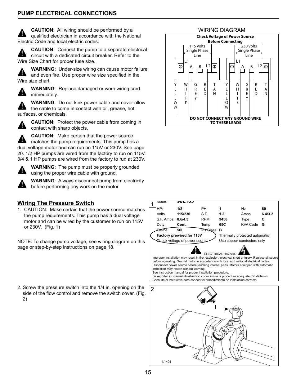
15 pump electrical connections, 1wiring the pressure
Everbilt Shallow Well Jet Pump Wiring Diagram Troubleshooting
Shallow Well Jet Pump Installation Diagram — UNTPIKAPPS


47 Gould Century Motor Wiring Diagram Wiring Diagram