Rotork Motor Operated Valve Wiring Diagram
Kevin g dewall created date: The control circuit operation described herein is for a rotork syncropak actuator.

Limitorque L120 Wiring Diagram Free Wiring Diagram
Your email address will not be published.

Rotork motor operated valve wiring diagram. Rotork controls is headquartered in bath, england, with its north and south america manufacturing Rd & bk are connected to the power, wt & yw are connected to the controlled wiring. 5 1 rising stem valves top mounting 11 5 2 valve with gearbox side mounting12 5 3non rising stem valves top mounting12 5 4 handwheel sealing 12 5 5 iqm modulating actuators 12 5 6 iqml linear drive unit 12 5 7 iqml adjusting linear stroke 13 6 cable connections configuration settings contents 14.
As with other rotork designs, the reaction force on the wormshaft, in direct proportion to the output torque is used to trip the 'open' and 'close' adjustable torque switches. Rotork electric actuators a range id 9929835 product details. Rotork motor operated valve wiring diagram.
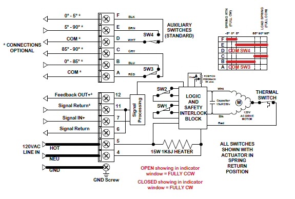
When the sw is open , the valve closed 4. Class f insulation as standard. Leave a reply cancel reply.
Hf21kj005 actuator motor wiring schematic image wiring diagram. Using an optional snap on wire harness adapter will simplify the wiring. For specific ratings and wiring diagrams, consult rotork, inc.
Rotork actuator parts wiring schematic diagram. Toyota radio wire harnesses 1987 and newer as viewed from mating end of connector c d a b h i f g e k j n m l. This section will familiarize students with basic rotork control circuit operation.
Spare parts for rotork iq90 electric valve actuators china. Motor operated valve wiring diagram source: Rotork is the home of the flagship iq intelligent electric actuator range.
0421 e112 motor operated valves course 02 section 2 4 rotork actuators. Wiring diagram limitorque mx 10 auto electrical wiring diagram. Wiring diagram 1995 ford f150 wiring diagram.
Toyota cq ts7471a 86120 12880. We understand this kind of rotork actuator wiring diagram graphic could possibly be the most trending subject once we portion it in google gain or facebook. Bl & gy connect with the valve’s fully open signal wiring 5.
The motor thermostat, when using the esd function, the hazardous area certification will be invalidated. 1.3 care for fluid power components fluid power components (actuators, solenoid valves, air sets, etc) should have protective plugs placed in their Search for rotork documents, publications, literature, product catalogues, manuals
Yw & wt connect with the valve’s fully closed. Rotork motor operated valve wiring diagram. A limited number of u.s.
1967 corvette wiper motor wiring diagram furthermore wiper motor wiring diagram also 1968 gto fuse box. • rf valves® should be transported and stored in the open position. The iw range of quadrant wormgear valve operators is available in manual and motorized configurations and features a removable sleeve to facilitate bore and keyway machining.
Gearboxes & valve accessories instrumentation & control pneumatic valves & manifolds. Cr7 04 wiring diagram (7 wires control, with feedback signal) 1. Wiring diversification, according to the customer equipment voltage is different, line number is different, provide different wiring mode.
Gm alternator wiring gm alternator wiring. • rf valves® are to be protected against mechanical damage or force (shock, blow, vibration, etc). Toyota 1971 fj40 wiring diagrampdf.
Rotork valve actuator wiring diagram pub002 004 00 0813 screw thermostat. Its submitted by organization in the best field. Alternator wiring diagram wiring diagram is the visual representation of a intricate electric circuit.
Control and indication where the actuator build allows remote control and indication supplies higher than 150v a.c. Wiring diagram house light fixture wiring diagram. Electric quarter turn high torque electric actators.
Wiring diagram rotork actuator trailer png 612x763px area electrical wires cable engineering free. (refer to actuator wiring diagram) the remote control and indication supplies must be derived from a. Describe the meaning of the g w in diagram component r.
When the sw is closed , the valve open 3. Here are a number of highest rated rotork actuator wiring diagram pictures on internet. The first component is symbol that indicate electrical element from the circuit.
Motor operated valve wiring diagram can be a variety of, can be 2 lines, 3 lines, 4 lines, can also be connected with a feedback signal line, 2 lines can also be with ground wire. When you make use of your finger or perhaps the actual circuit with your eyes it is easy to mistrace the circuit. Reduced internal wiring and connections.
Rotork iq3 range actuators remote wiring schematics. Rotork is the global market leader in valve automation. Required fields are marked *.

Rotork Motor Operated Valve Wiring Diagram Wiring Diagram Schemas
Rotork Motor Operated Valve Wiring Diagram Wiring Diagram Schemas

100b00006 Electrical Components Computer Engineering


Mov Rotork Wiring Diagram AHEALTHYJEN
Rotork Motor Operated Valve Wiring Diagram Wiring Diagram Schemas

Rotork Motor Operated Valve Wiring Diagram Wiring Diagram Schemas

Rotork Motor Operated Valve Wiring Diagram Wiring Diagram Schemas

20 Inspirational Auma Actuator Wiring Diagram
Rotork Motor Operated Valve Wiring Diagram Database

Patent US6079442 Valve actuator Google Patents

Rotork Actuator Wiring Diagram Collection
Wiring Diagram Motor Operated Valve HENWRITHINGS
Rotork Motor Operated Valve Wiring Diagram Database

[DIAGRAM] Wiring Diagram Rotork FULL Version HD Quality Diagram Rotork PAINDIAGRAM.ARGISO.IT

Rotork Motor Operated Valve Wiring Diagram Wiring Diagram Schemas

Patent US5239874 Method of monitoring the condition of a motor operated valve system Google
Rotork Wiring Diagram Pdf COCOSWEETPEA

Rotork Motor Operated Valve Wiring Diagram Wiring Diagram Schemas

Rotork Motor Operated Valve Wiring Diagram Wiring Diagram Schemas